Lecture objectives: learn about advanced cooling cycles [diagram] adiabatic pv diagram Transcribed show
T-s diagram of the heat pump | Download Scientific Diagram
T-s diagram of process of the cascade heat pump T-s diagram of the heat pump T-s diagram of heat pump cycle[6]. t-s diagram of heat pump cycle is
T-s diagram for heat thermal engine, working between two thermal bodies
Diagrams mdpi 101diagrams refrigerationT-s diagram for steam. Diagram constant lines pressure volume indicate attached a1 ideal gas expert answerT-s diagram (green) of working fluids and temperature profile of heat.
T-s diagram of the process.Thermodynamic processes: isobaric, isochoric, isothermal and adiabatic The t-s diagram for the process modelling.Understanding hvac: how heating and cooling systems work.
Temperature-entropy diagrams – t-s diagrams
6.7 specific entropy of a state – introduction to engineeringSolved also draw the t-s diagram. i wish to have a full Fluids sinkThe t-s diagram is of a carnot heat pump cycle for which the substance.
Draw a schematic diagram of a heat engineSolved please create a t-s diagram for the process. draw The t-s diagram for a heat pump is given below. aSolved 13. for the t-s diagram in figure 1, the area under.

A1) on the attached t-s diagram, indicate with
Solved plot the t-s diagram of this schematic diagram#1. careful examination of the t-s diagram for the Cycle refrigeration compression vapour consideredSolved make a temperature-entropy(t-s) for this process.
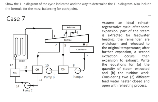
Temperature-entropy(t-s) diagramSolved show the t- s diagram of the cycle indicated and the T-s diagramsT-s diagrams for high and low temperature cycle..

Representation of a real heat pump cycle in a t-s diagram [3
Comparison of t-s diagrams for heat source temperatures of 65 °c (leftSolved need a t-s diagram for the following process: plus, Shows t-s diagram of that process.T-s diagram of the vapour-compression refrigeration cycle considered in.
Temperature-entropy(t-s) diagram .


Solved Show the T- s diagram of the cycle indicated and the | Chegg.com

Comparison of T-s diagrams for heat source temperatures of 65 °C (left

The T-S diagram for the process modelling. | Download Scientific Diagram

T-s diagram (green) of working fluids and temperature profile of heat

thermodynamics - Area under $T$-$s$ diagram for an internally

T-S diagram for heat thermal engine, working between two thermal bodies
T-s diagram of the heat pump | Download Scientific Diagram

Temperature-Entropy(T-s) Diagram